-
 Creating the Current Sensor Board
- Date Tue 16 February 2016
- By Jason Jones
- Category current-sensor
- Tags current-sensor
Intro
There have been several times that I have had to sense current in an application for one reason or another. I was working on just such an application recently when I thought to myself, "Hey, why don't I just make a quick solderable module and just always use that". So I did.
Requirements
I want a current-sensor board that will give me unidirectional current sense output that I can run straight into an A/D converter. I am looking for a maximum sense current around 3A, and the ability to handle a voltage of at least 30V.
The Market
SparkFun has their current sensor breakout board for the INA169. It is a very flexible layout with four nice mounting holes and is about the size of a quarter (as shown on their website), which I believe is 1" x 1". In truth, it is a really nice board and there is no recommendation that I can make against it. I just wanted something a bit more specific. Here are the items that I wish to address:
- The first is that the breakout board is so generalized that it wastes a lot of space on components that will never be populated. I want something small and purpose-built.
- The output is a relatively high-impedance output, meaning that if you want to run it straight into your ADC, then you may need to roll an opamp into your circuit.
- Lower-voltage part (the INA139 is a bit cheaper and still goes up to 40V).
- In stock.
The 'in stock' part is probably what got me going down this path, but the rest of the items are things that I decided that I wanted along the way.
I looked at other options as well. For instance, the "AttoPilot boards are not bad, but they are scaled for currents greater than 10x the range I am looking for and cost \$20/board. The boards based on the ACS712 chip are really great, but they have a quiescent current in the 10mA range. I am doing a project for a battery-powered application, so this will not do.
Schematic
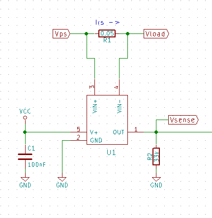
Building the schematic was probably the easiest part. TI basically gives you the schematic in their datasheet, you just have to pick parts and place them.
I chose a 0.05ohm resistor as my sense resistor. I was trying to balance sense voltage with power loss. At 0.05ohm, there will be a 150mV differential voltage across the sense resistor which is directed into the INA139 IC.
I chose a 33kohm resistor as the 'gain' resistor. I am expecting about 2A nominal in my circuit and I want to be able to sense up to 3A. At 3A, there is a 150mV differential (as previously descussed), which - when amplified by 33 - will result in a 4.95V output. Since I am using a 5V microcontroller for the application, 33kohm is about right.
At this point, the circuit looks a lot like the Sparkfun schematic. But wait, there's more!
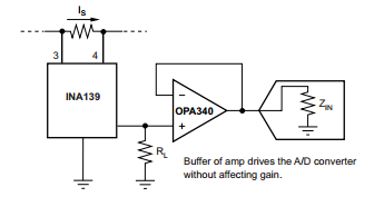
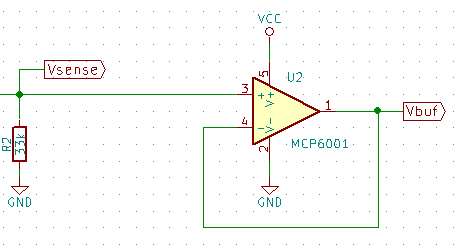
The IC output in combination with the resistor form a high-impedance output. The TI datasheet recommends a buffer on this before utilizing it on any A/D converter, so I took the trouble to place a small voltage follower on the board to make it A/D compatible:
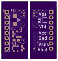
The last point on the schematic is to place some sort of external connector on the board. I prefer 0.1" headers whenever possible since they are universally available, so I placed an 8-pin header with the power-supply and load pins doubled-up for more current-carrying capacity.
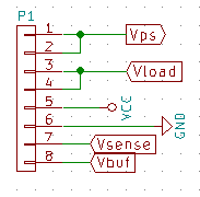
Through the header, we can supply the current to be measured by running a current from Vps to Vload. We can supply the ICs with the power through Vcc and GND. Finally, we can access the current sensor directly through Vsense or the buffer through Vbuf. Perfect!
Layout
As us usual with layouts, there isn't much to say about the actual process. We placed the header on the edge of our board and crammed everything into as small a space as was reasonable. At the end, we ended up with a board that is 1.1" x 0.5", whoohoo! Mission accomplished!
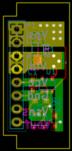
There are layers two cutouts which are to 'bottom' against a PCB when this board is inserted into another board.
The sense resistor is also connected to planes which have vias. This provides a small amount of heatsinking for the potentially hot component.
Finally, we added labels to the bottom side to help the user (probably just me). There is a line drawn that indicates the direction of current if it isn't clear by the lettering. The KiCad view is a bit busy. The OSH Park view is much better (below). You can see the vias much more clearly on the OSH Park render.
So, we have already ordered boards from OSH Park, next we need to order parts and get them soldered up and ready-to-roll!
As usual, all files can be found on github.
- article
- current-sensor
- curve-tracer
- dispatch
- fan-controller
- fixed-point-math
- load-cell-sensor
- meta
- reference


 RSS
RSS
2
assembly
5
buffer
31
c
3
current sensor
28
curve tracer
2
fan controller
6
fixed-point math
4
interrupt
3
KiCAD
3
labview
5
layout
6
msp430
4
pelican
18
pic24
29
project
12
python
2
Q1.15
4
schematic
10
serial
3
solidworks
2
task manager
2
theme
3
tkinter
9
uart
9
xc16