-
 Current Sensor Board - Testing with a DC Motor
- Date Fri 18 March 2016
- By Jason Jones
- Category current-sensor
- Tags current-sensor current sensor project dc-motor
In previous posts, we tested the DC performance of the current sensor board. In this post, we are going to test the current sensor board using a typical toy DC motor as the load.
DC Motors
A DC motor runs from a DC power supply, but the motor currents are typically not very flat due to primarily to the motor commutating (when the brush moves to a different coil on the armature). Electrical and magnetic variances play a role as well.
As the motor rotates, the brushes of the motor contact the same points over and over again. Given a constant load, the variances in the current waveform are very consistent over a motor rotation, which means that we could potentially use the motor current frequency to measure speed, but I digress. We will take a peek into this later.
The point I'm really getting at is that DC motors do not draw a constant current, regardless of what your multimeter tells you. The current waveform is very peaky. This is what we want to see with our current sensor.
Our Setup
Board Mod
The first test that I ran revealed that the gain was a bit high. We had a 33kΩ resistor and the peaks were being cut off. We modified the resistor to a 22kΩ, which allowed us to complete our test.
Using a 22kΩ resistor, our transimpedance - or volts per amp - is now 11Volts/Amp.
Circuit
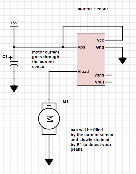
C1 on Vps
The first test that we will run will be with C1 placed between the power supply voltage and ground. This test will show the motor peak currents very clearly since all motor current will be going through the shunt resistor on the current sensor board.
C1 across Motor
The second test we will run is with C1 across the motor. In this situation, we expect C1 to supply a majority of the instantaneous current requirements of the motor and the current sensor will detect a much more average value of current.
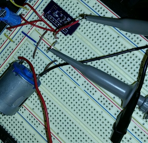
Breadboard Setup
For ease, we ran this experiment on a typical breadboard. Our typical expected currents are less than 300mA, so the board contact resistances shouldn't interfere with the result.
Results
C1 on Vps
Our first picture reveals a high peak-to-peak current (blue) and a
slightly wavy voltage across the motor terminals (yellow). The
voltage difference is due to the peak currents through the motor.
Since we have a resisor in line with the motor, as the current
increases, the resistor voltage increases, decreasing the voltage
across the motor. Notice how the peaks in current correspond to
the dips in the voltage.

Our next picture has some measurements. Earlier, we stated that the current waveforms are repetitive. You can see that in these scope captures. With a 2-pole, 3-slot configuration (most common in toy motors), the cycle repeats every 6 peaks. Each peak corresponds to one commutation of the motor. Six commutations result in one revolution of the motor.

The mechanical period of this motor is 7.14ms. Thus the speed is:
frequency = 1/7.14ms = 140Hz speed_in_rpm = 140rotations/sec * 60sec/min = 8403rotations/min
Not bad! You could do the same math on the period of the current peaks, but these peaks aren't nearly as consistent as the rotational period. If you measure the motor period, just count out 6 peaks and you will get a much more consistent value. Otherwise, your PID loop will get wrong input values for the speed and you will notice a vibration in your motor that you are actually causing!
Finally, our highest and lowest voltages measured are 4.0V and 960mV for a peak-to-peak voltage of 3.04V. Translating to current:
Ihigh = 364mA
Ilow = 87mA
Ipp = 277mA
That is quite a variation in current! If you are running your arduino on the same circuit as this motor, you'd better do something about that!
C1 across Motor
We have made one change to our schematic. Instead of C1 being placed across Vps and ground, we have placed it directly across the motor.

You can see a dramatic change in the current waveform. Note that the rotational variation still repeats, but our current is much closer to the average current.
| Parameter | C1 on Vps | C1 on Motor |
|---|---|---|
| Ihigh | 364mA | 221mA |
| Ilow | 87mA | 160mA |
| Ipp | 277mA | 61mA |
What a difference!
Notice also that the voltage across the motor (yellow) is nearly constant.
Conclusions
We can easily measure motor current with the current sensor board. Additionally, the characteristic waveforms of the motor current can reveal aspects of motor operation that may not even be apparent to the user.
It is also important to note the importance of capacitance in protecting your cirucit from the large noise spikes caused by the typical DC motor. One need only look at the plots to see the huge differences between the two configurations.
- article
- current-sensor
- curve-tracer
- dispatch
- fan-controller
- fixed-point-math
- load-cell-sensor
- meta
- reference


 RSS
RSS
2
assembly
5
buffer
31
c
3
current sensor
28
curve tracer
2
fan controller
6
fixed-point math
4
interrupt
3
KiCAD
3
labview
5
layout
6
msp430
4
pelican
18
pic24
29
project
12
python
2
Q1.15
4
schematic
10
serial
3
solidworks
2
task manager
2
theme
3
tkinter
9
uart
9
xc16