-
 Project Curve Tracer: Configuring the UART
- Date Fri 11 March 2016
- By Jason Jones
- Category curve-tracer
- Tags curve-tracer c curve tracer interrupt pic24 project serial usb xc16
Intro
We have the most basic elements of the curve tracer working, but we have no way to interface with it other than hooking up the Microchip debugger and downloading array variables. In this installment, we are going to make the first steps toward getting data to the PC using the UART. You may know this better as a USB serial port.
Data Requirements
We are operating on a human time scale, so our data requirements are likely not very high. Going through a few data points to get us started on a requirements calculation:
- It takes two bytes/sample
- Both current and voltage must be sampled
- The lowest frequency setting will probably be around 60Hz
- The waveform generator is operating with a period of 83.2μs
The lowest frequency will have the most points to transfer. Our 60Hz signal has a period of 16.7ms. This means that there are
16.7ms/83.2μs = 200.7 points to save
With 200 points, 2 bytes/point, and both current and voltage to save:
200points * 2bytes/point * 2terms * 8bits/byte = 6400 bits
We have 6400 bits to send per waveform. If we wanted to send all 6400 bits on every waveform, we would be sending:
6400bits/waveform * 1/16.7ms = 400000bits/s
That is quite a number! We will likely do some averaging and filtering on the uC, and a person doesn't need a refresh rate higher than 8 times per second on a periodic waveform, so lets make that assumption:
6400bits/waveform * 8 = 51200bits/s
As it happens, there is a 'standard' value that is very close to this value at 57600 bits/s. We will select this for now, knowing that we may need or want to modify it later.
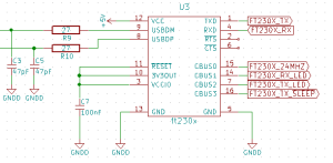
Soldering the Parts
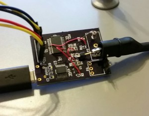
We haven't bothered populating the FT230X part until now largely because it wasn't necessary and might actually end up compromising our ability to debug the board and software. We now wish to populate the FT230X, the USB connector, R9 and R10. The schematic says that we will populate R9 and R10 with 27Ω resistors, but I didn't have any, so I populated with 0Ω resistors. That seems to have worked out OK.
Setting up the Registers
Baud Rate Generator
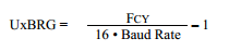
The baud rate generator for this device operates in two modes, 'standard' and 'high-speed'. Generally, we want standard whenever possible because high-speed mode is prone to more error. We get the above equation from the datasheet. Using 12MIPS as the FCY and 57600 as the baud rate, we calculate 12.02 as the value for U1BRG. Since this is nearly an exact integer, we will have very little error. If the value had been 12.5, we may have wanted to select a different baud rate that fell closer to an integer value to reduce the error.
Setup of Registers
In most peripherals, the setup order doesn't matter. With this particular peripheral, the setup order matters. I spent an hour trying to figure out why my setup wasn't working and it turns out that it was the order that I had executed the statements in. Here is the order you should follow for the UART peripheral:
- Setup the ANSB bits to a digital state
- Setup the core UART registers with the UART disabled and UTXEN disabled
- Setup interrupts
- Enable UART with UARTEN
- Enable UTXEN
If you don't follow this order, the peripheral won't function! I'm not sure why, but it doesn't. Resulting code:
1 2 3 4 5 6 7 8 9 10 11 12 13 14 15 16 17 18 19 20 | void initUart(void){
ANSBbits.ANSB2 = DIO_DIGITAL;
ANSBbits.ANSB7 = DIO_DIGITAL;
/* baud rate = 57600bps
* U1BRG = (12000000/(16*57600)) - 1 = 12.02 = 12
*/
U1BRG = 12;
U1MODE = 0x0000; // TX/RX only, standard mode
U1STA = 0x0000; // enable TX
/* uart interrupts */
IFS0bits.U1TXIF = IFS0bits.U1RXIF = 0;
IEC0bits.U1TXIE = IEC0bits.U1RXIE = 1;
U1MODEbits.UARTEN = 1;
U1STAbits.UTXEN = 1;
return;
}
|
For testing purposes, I initially configured the receive interrupt to echo its value through the transmit register. This way, when I type a character into the terminal (we will get to that), it will be displayed on the screen.
The test environment tends to 'skid' in MPLAB X, so setting a break point at a particular line is not very reliable. I added several Nop() function (no operation) and set a break point on the top. This allowed me to test the transmit interrupt as well.
1 2 3 4 5 6 7 8 9 10 11 12 | void _ISR _U1TXInterrupt(void){
Nop();
Nop();
Nop();
IFS0bits.U1TXIF = 0;
}
void _ISR _U1RXInterrupt(void){
U1TXREG = U1RXREG; // echo
IFS0bits.U1RXIF = 0;
}
|
Connecting to the Terminal
Terminal Download
If you don't currently have a terminal program, there are several out there. My favorite for windows is PuTTY. When I'm on Linux, I use minicom (apt-get install minicom), but I have to look things up every time to use it. You won't have to install PuTTY, just download it and execute.
Terminal Setup
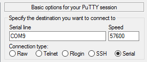
Open PUTTY.EXE and enter the appropriate values under the 'Session' tab. My PC has populated the USB serial port as 'COM9', but yours will likely be different. Press the 'Open' button at the bottom and you should see a black box with a small green square in it. If everything is working correctly, you should be able to type in that box. What is actually happening:
- You type a letter into the terminal
- The terminal converts that letter into its numeric equivalent and sends that to your board
- Your board generates an interrupt, executing the _U1RXInterrupt() function
- The interrupt function reads the byte from the receive register and sends it to the transmit register
- The terminal receives the number and displays it to the user
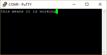
You now have the capability to send any 8-bit number between the PC and the microcontroller! Pretty cool, huh?
Next Steps
This post marks the end of hardware verification. We have soldered all components to the board and verified basic functionality of all elements. In our next post, we will review what we have done thus far and make the minor corrections to the schematic and layout that have been noted throughout the project, but haven't fully been collected to this point.
After completing the next round of schematic and layout, we will move almost exclusively to the software realm. We still have some work to do with the serial interface.
- article
- current-sensor
- curve-tracer
- dispatch
- fan-controller
- fixed-point-math
- load-cell-sensor
- meta
- reference


 RSS
RSS
2
assembly
5
buffer
31
c
3
current sensor
28
curve tracer
2
fan controller
6
fixed-point math
4
interrupt
3
KiCAD
3
labview
5
layout
6
msp430
4
pelican
18
pic24
29
project
12
python
2
Q1.15
4
schematic
10
serial
3
solidworks
2
task manager
2
theme
3
tkinter
9
uart
9
xc16