-
 Curve Tracer Reference
- Date Tue 13 June 2017
- By Jason Jones
- Category reference
- Tags reference curve tracer project
Purpose
This document is intended to document the curve tracer This document will be updated through revisions and can be used as a persistent reference, regardless of the 'date posted'. As more information becomes available, documentation will be added.
The original post for the curve tracer can be found here. Note that the specifications have changed somewhat since project inception based on hardware limitations and other factors.
Current Revision
The current revision for the Curve Tracer is 1.2. The schematic and layout may have minor revisions released independently, depending on the scope of the change.
| Document | Current Revision | Location |
|---|---|---|
| Curve Tracer Assembly | 1.2 | github |
| Schematic/BOM | 1.2 | github |
| Layout | 1.2 | github |
| Firmware | -unreleased- | github |
| Desktop GUI | 0.1.0 | github |
A "working" revision of all of the above may be found in the github repository.
Hardware
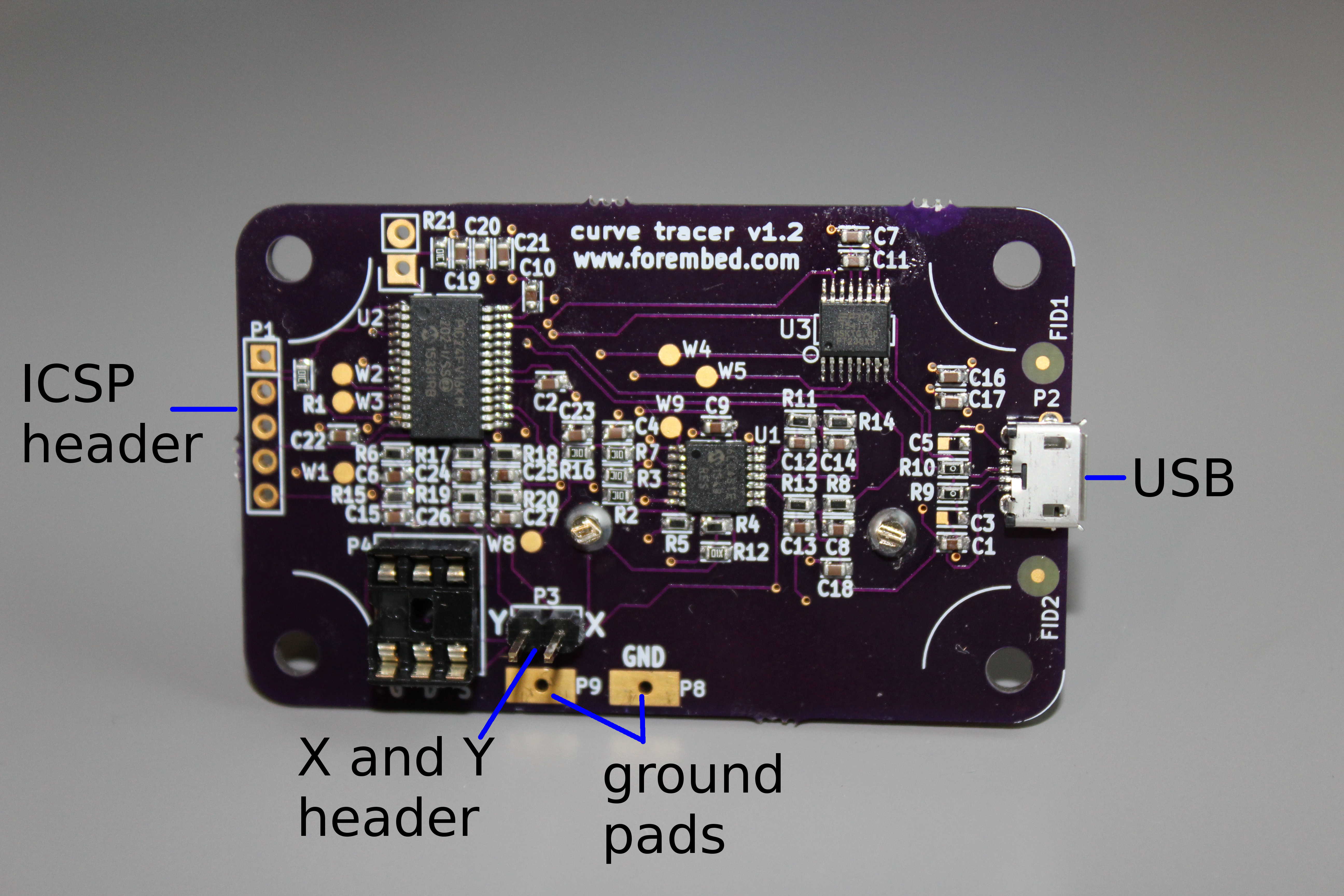
| Connection | Description |
|---|---|
| P1 | Header, 0.1", utilize for flash programming the microcontroller using a Microchip ICD3 or similar. |
| P2 | USB Micro-B Connector utilized to create a Virtual COM Port for PC connection. |
| P3 | XY header connection for probe tip terminals of an oscilloscope probe. |
| P4 | Socket, 0.1", utilize to place a TO-220 or other through-hole components to be traced. |
| P8, P9 | Pads for easy connection to the GND terminals of an oscilloscope probe. |
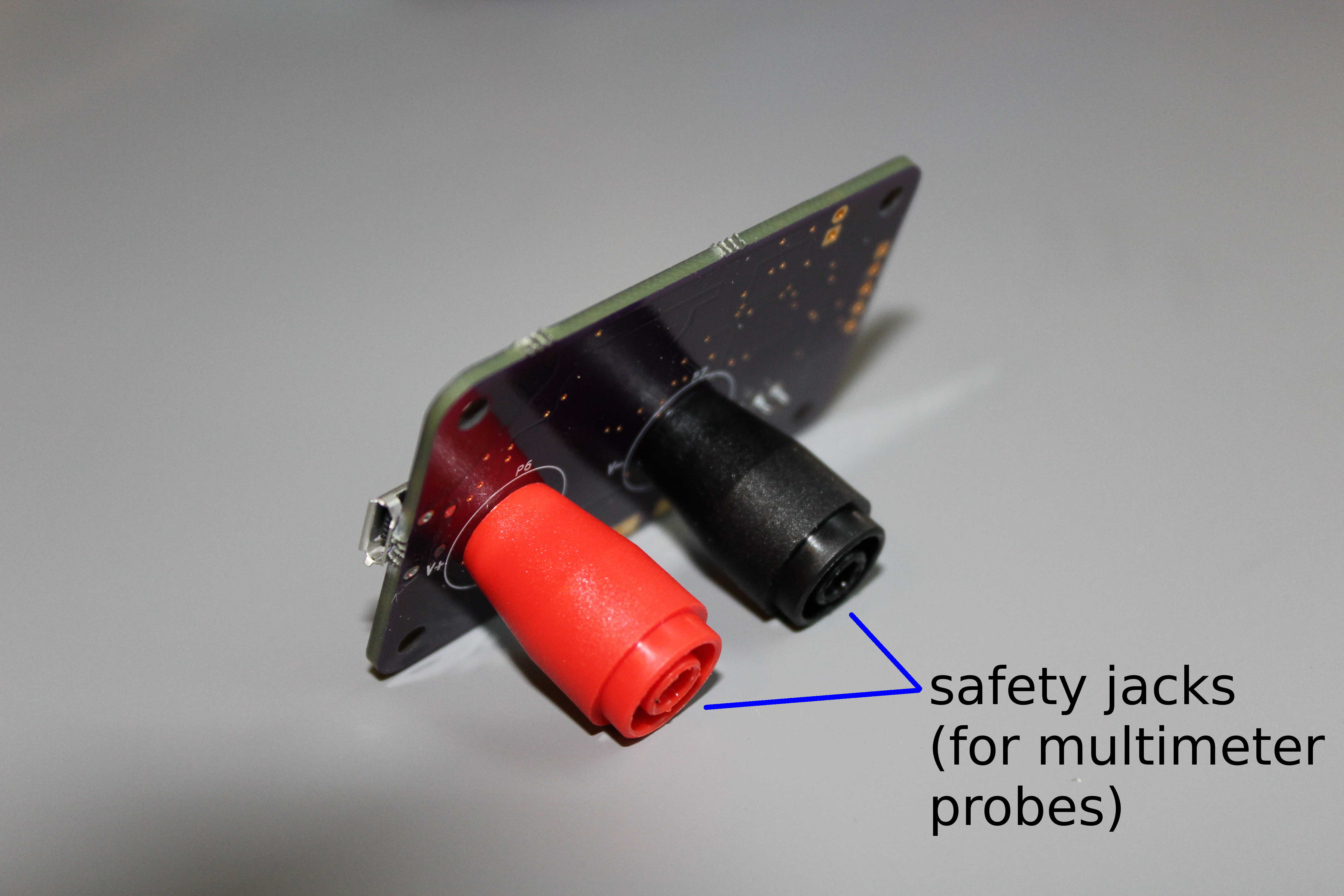
| Connection | Description |
|---|---|
| P6 | Safety (multimeter) probe connector, 'positive'. |
| P7 | Safety (multimeter) probe connector, 'positive'. |
Connector Details
Each multiple-contact connector is detailed in this section. Connectors with a single function - such as USB - are not detailed.
ICSP - P1
| Pin | Description |
|---|---|
| 1 | ~MCLR/Vpp |
| 2 | +5V |
| 3 | GND |
| 4 | PGD |
| 5 | PGC |
Probe Connections - P6, P7
| Pin | Description |
|---|---|
| P6 | V+, positive probe connection. |
| V- | V-, negative probe connection. |
MOSFET/Transistor Connection, P4
| Pin | Description |
|---|---|
| 1 | A high-impedance voltage output intended to apply a voltage to a MOSFET or similar high-impedance device, also called the 'gate' |
| 2 | Positive probe connection, 'drain' |
| 3 | Negative probe connection, 'source' |
| 4 | 'drain' |
| 5 | 'source' |
| 6 | 'gate' |
Pin Specifications
| Parameter | Value |
|---|---|
| Maximum Absolute Voltage, V+, V- | 5.0V |
| Minimum Absolute Voltage, V+, V- | 0.0V |
| Maximum Differential Voltage, V+, V- | 5.0V |
| Minimum Differential Voltage, V+, V- | -5.0V |
| Maximum Current, V+, V- | +/-20mA |
| Maximum Absolute Voltage, Vgate | 5.0V |
| Minimum Absolute Voltage, Vgate | 0.0V |
| Maximum Current, Vgate | 2.5mA |
| Output Impedance, Vgate | 2kΩ |
Firmware
If you have received units from me, then you do not need to compile or program the board! You may skip this section! If you have built the boards yourself, then you will want to download, compile, and load the firmware.
In order to compile and load the firmware yourself, you will need MPLAB X and the XC16 Compiler installed on your machine.
- Create a new project in MPLAB X (File -> New Project)
- Select 'standalone project'
- Select the device - PIC24FV16KM202
- Select the directory in which you would prefer to save your project
- Select the XC16 compiler, then the debugging tool that you will be using for programming (probably an ICD3 or PICkit)
- Add all
*.hfiles into the 'headers'. - Add all
*.cand*.sfiles into the 'source' - Enter the compiler configuration and select optimization
-O1or the compiler may not be able to allocate enough program memory. I usually like to isolate each function into its own section and tell the linker to remove unused sections in order to reduce memory usage. - Program your board!
You will also need to change the configuration of the FT230X. Detailed instructions may be found on the blog.
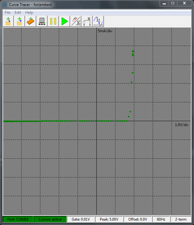
GUI
The GUI is written in Python 3. Does this mean you need to install Python or know how it works? No! There are three options for installation:
- native Python (pip-installed)
- native Python (setup-installed)
- download executable
The GUI should work on all development environments that support python 3
(windows, linux, mac). Note that linux installations may require that certain
libraries be installed. On debian based systems, these would be installed
using apt:
$> sudo apt install python3-dev python3-setuptools python-imaging python3-pil.imagetk
$> sudo apt install libjpeg-dev libtiff4-dev zlib1g-dev libfreetype6-dev libwebp-dev
$> sudo apt install tcl-dev tk-dev
User documentation will be available in a readthedocs format soon!
Pip-Installed
Execute pip install curve_tracer in your root Python or in your virtual
environment. Once it is installed, then simply curve_tracer on the
command line should open the GUI.
Setup-Installed
Clone the git repository,
navigate to the /curve_tracer_gui directory, and python3 setup.py install.
Once installed, simply type curve_tracer in your command window to
begin the GUI.
Executable (Windows)
For the windows users, we have utilized pyinstaller to create a single-file executable that does not require installation of the python environment. Simply download the executable from the github releases and enjoy! Still working on linux, guys...
User Notes
When this equipment is utilized as a curve tracer, it MUST be utilized without power applied to the unit under test (UUT). There are many varieties that emulate power off by going into a standby state, but this is NOT power off! Be sure that the device is completely unplugged and leave unplugged for several seconds to give any capacitors time to discharge.
Vgate is intended to hold a constant DC voltage across the gate of a MOSFET. Any resistive load placed on Vgate will potentially load Vgate beyond its driving capacity.
- article
- current-sensor
- curve-tracer
- dispatch
- fan-controller
- fixed-point-math
- load-cell-sensor
- meta
- reference


 RSS
RSS
2
assembly
5
buffer
31
c
3
current sensor
28
curve tracer
2
fan controller
6
fixed-point math
4
interrupt
3
KiCAD
3
labview
5
layout
6
msp430
4
pelican
18
pic24
29
project
12
python
2
Q1.15
4
schematic
10
serial
3
solidworks
2
task manager
2
theme
3
tkinter
9
uart
9
xc16