-
 Project Curve Tracer: Configuring the Oscillator
- Date Thu 10 March 2016
- By Jason Jones
- Category curve-tracer
- Tags curve-tracer c curve tracer pic24 project xc16
If you have no idea what this is about, go back to the Curve Tracer Requirements Post!
Intro
In previous posts, we have been using the maximum speed 32MHz (16MIPS) oscillator. This oscillator is prone to some error and we would like to eliminate that error. In this post, we are going to use the FTDI calibrated oscillator at 24MHz to drive our chips clock input.
Setting up FTDI Chip
Desired FTDI Setup
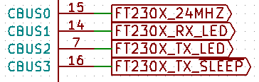
The first thing that you must do is set up the FTDI chip itself so that it outputs the 24MHz waveform desired. The part we are using is the FT230X (pdf warning). We must download the FT_PROG utility from the FTDI site before going too far as well. This utility allows us to flash the EEPROM of the FTDI board, which sets up the FTDI pins. The default configuration is:
- CBUS0 = TXDEN
- CBUS1 = RXLED
- CBUS2 = TXLED
- CBSU3 = SLEEP
We aren't using RXLED or TXLED, so those outputs defaults are correct as-is. Additionally, the SLEEP pin is correct by default as well. The only pin that we need to change is CBUS0.
Changing the EEPROM
Plug the USB device into your PC. Allow the drivers to install.
The FT_PROG utility appears to only work in Windows. I didn't try it in Linux. When it first opens, it is pretty blank. Go to DEVICES -> Scan and Parse in order to have a look at your device options.
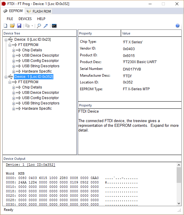
My scan resulted in two chips. Only one of the two devices was of the FT230X type, so that was easy enough to identify. I verified by unplugging, scanning, and re-plugging and re-scanning.
Click down into the tree, Hardware Specific -> CBUS Signals. When you click on 'CBUS Signals', the right pane will display the Cx signals under 'Property' and their current values under 'Value'. Click the drop-down box by 'C0' and select the 'CLK24MHz' option. Then click the lightning bolt shortcut at the top of the window to program.
In the 'Program Devices' dialog box that comes up, ensure that the proper device is selected and click the 'Program' button.
Verifying Output Frequency
Of course, we can't just flash the EEPROM and call it done, we have to verify that it worked! Using the oscilloscope, we can see the the pin is outputting the expected 24MHz frequency.

Micro-Controller Code
Before you get started...
You are using some tool to power your board. Up to this point, I have been using the MPLAB ICD3 to power the board. We are about to change to USB power, so before you connect your programmer, go to the ICD3 options and turn off the ICD3 power supply.
Its all in the Configuration
Up to this point, we have been using the internal oscillator to perform operations on the uC. We would like to use the clock input pin instead. We should only need to change the configuration bits. FNOSC should be changed to 'PRI' to select the primary oscillator (instead of the internal oscillator). POSCMOD should be changed to 'EC' in order to select the external clock as the primary oscillator.
1 2 3 4 5 6 7 8 9 10 11 12 | // FOSCSEL
#pragma config FNOSC = PRI //(changed to PRI)
#pragma config SOSCSRC = ANA
#pragma config LPRCSEL = LP
#pragma config IESO = ON
// FOSC
#pragma config POSCMOD = EC //(changed to EC)
#pragma config OSCIOFNC = CLKO
#pragma config POSCFREQ = HS
#pragma config SOSCSEL = SOSCHP
#pragma config FCKSM = CSECME
|
Window -> PIC Memory Views -> Configuration bits will get you to a window which will help you select the options using drop-down menus. Once your options are selected, click 'Generate Souce Code to Output' and copy/paste as necessary into 'main.c'.
Verification
Using the oscillocope, we can verify that the frequency has changed by simply looking at the period at which the output is updated. Measuring pre-configuration change yields an update of the output waveform every 62.8μs. After the change, the update occurs every 83.2μs. This holds the same ratio as 12/16, so we are good. We are now connected to USB power and are using the FTDI 24MHz calibrated clock as our clock input!
Our next post will (probably) be setting up the serial port function so we can finally begin speaking with the PC.
- article
- current-sensor
- curve-tracer
- dispatch
- fan-controller
- fixed-point-math
- load-cell-sensor
- meta
- reference


 RSS
RSS
2
assembly
5
buffer
31
c
3
current sensor
28
curve tracer
2
fan controller
6
fixed-point math
4
interrupt
3
KiCAD
3
labview
5
layout
6
msp430
4
pelican
18
pic24
29
project
12
python
2
Q1.15
4
schematic
10
serial
3
solidworks
2
task manager
2
theme
3
tkinter
9
uart
9
xc16