-
 Fan Controller Introduction
- Date Mon 11 July 2016
- By Jason Jones
- Category fan-controller
- Tags fan-controller project fan controller
Sorry that it has been so long since our last post. I have been out on vacation for a bit with some family and am just getting back into the swing.
PC Fan Controller
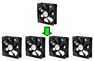
I recently wished to add a fan to my PC and I realized that I only had a couple of PC fan case headers where I would have liked to have more. I ended up purchasing a set of fans that can be daisy chained, but I don't actually like that solution very much.
I did a quick Tindie search and I found that the best candidate is a fan controller based on temperature and not on the motherboard command.
A github search shows several arduino fan controllers, but nothing that is a open-source and cost-effective.
After a bit of thinking about it, I sketched out some basic requirements for a simple fan controller.
I Know This Has Been Done Before
Before you go into the "hey, this has been done", I get it. It has. I want to do it and I think it is still cool and fun. Get over it.
Requirements
The basic requirements for the PC fan controller are as follows:
- Must be easy for the user to adjust the speed of a particular fan
- Must scale the input PWM value properly for each fan setting
- Fan settings must be persistent through power cycling
- Each fan will soft-start and in-sequence to reduce load on the motherboard
- Must be directly pluggable
I thought about adding serial ports and other features to the board, but decided against it in order to reduce complication and - perhaps - speed up the design stage. The user interface will be through a single knob, which is a quadrature encoder with a push function.
State Diagram
The initialization state will initialize all microcontroller values that need to be initialized.
The start state will go through a startup for each fan in a manner that reduces the overall current draw
of the fans.
The run state will read the motherboard command and scale the command to the other fans appropriately. For
instance, if the motherboard is commanding 50% duty cycle and the saved calibration value is 80% duty cycle
for FAN0, then the output value for FAN0 will be
or 40% duty cycle.
In the absence of a command from the motherboard, the board will assume a command of 100% from the motherboard and control the fans accordingly.
In order to reduce cost, it helps to only have one direct interface for the user which consists of a rotary encoder and a switch. The switch is actually the same quadrature encoder, just with an integrated switch that is actuated when the user pushes "down".
When the switch is pressed, the user will enter calibration mode. On each press of the switch, a different
fan is selected to calibrate and the others are all turned off. Once the user leaves the encoder and switch
alone for some number of seconds to be determined - or the timeout expires - then the values are saved and
the state moves back to start.

Schematic and Layout
Fortunately, PC fans are pretty simple devices, requiring open-collector outputs and pull-up inputs. Have a
look at the schematic. Note that we have pull-up
resistors on all sense lines and open-collector outputs for all output PWMs. I know that the microcontroller
pins support open-collector outputs, but I wasn't sure that one might be able to use these open-collector outputs
in conjunction with the PWM module, so I made those outputs external. This also provides a level of isolation
to the microcontroller pins that gives me some comfort.
The microcontroller is the same as that used for the curve tracer, which is a 16MIPS, 16-bit microcontroller. There are likely better choices for the microcontroller, but I have already used this one and I felt that I might help myself by using the same microcontroller across projects.
LEDs were included for visual debugging, although they will likely not be populated. When used in PWM applications, the brightness of the LED is an indication of the duty cycle.
The layout was similarly straightforward.
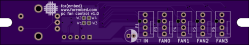
The primary fan connectors are all on the "top" side. This includes the in, which is where power and command
come from the motherboard and where the sense command from FAN0 is sent. Note that each fan connector is clearly
labeled and the small bus capacitor will be mounted to this side as well.
The schematic was created in a way that allows the encoder to be mounted on either side of the board.
A few test points - W1, W2, W3, and W4 - are visible from this side. These points are directly below the microcontroller and are exclusively for debugging purposes.
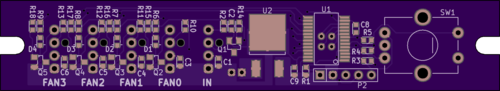
All SMT components are on this side, including the microcontroller. It is possible to mount the encoder on this side of the board. The majority of the schematic is located on this side.
As always, a github repository has been created to manage the project. At this time, I plan to keep the electronics and firmware in the same repository as the project is quite simple.
Timeline
I have placed the order from Digikey and Osh Park for the parts and boards. As this is a relatively simple application, I don't expect it to take very long to reach full maturity.
- article
- current-sensor
- curve-tracer
- dispatch
- fan-controller
- fixed-point-math
- load-cell-sensor
- meta
- reference


 RSS
RSS
2
assembly
5
buffer
31
c
3
current sensor
28
curve tracer
2
fan controller
6
fixed-point math
4
interrupt
3
KiCAD
3
labview
5
layout
6
msp430
4
pelican
18
pic24
29
project
12
python
2
Q1.15
4
schematic
10
serial
3
solidworks
2
task manager
2
theme
3
tkinter
9
uart
9
xc16