-
 Project Curve Tracer: XY Outputs
- Date Thu 14 July 2016
- By Jason Jones
- Category curve-tracer
- Tags curve-tracer c curve tracer
Oscilloscope XY Outputs are Working!
Using two PWM outputs and using a couple of simple RC circuits on the board, we have managed to get the XY outputs working well enough to display on any oscilloscope! I now feel that the hardware is feature-complete!
Status
The hardware in github is up to version 1.2, which is electrically identical to v1.0 and v1.1. The only changes have been to the interfaces in order to make it easier for you to connect your devices to the curve tracer.
Setting Up
You will be able to see the settings in our screenshots below, but it is always a good thing to state some of them explicitly.
The vertical offset for each trace is 2.5V. You may recall from the schematic that the voltage applied is 5V, so it stands to reason that the offset applied to each trace is half of that.
The X trace is set to 1V/division and the Y trace is set to 0.5V/division. This is somewhat arbitrary, but not as critical as the vertical offset. I have found myself with a few different settings for these values that work just fine.
Finally, the horizontal scale was adjusted so that at least one complete waveform is shown on the screen, which corresponds to 2.0ms/division.
Couple of Pics
I have a Rigol DS1054, which is a great oscilloscope for the price. I would like to see the XY on an old CRT screen for comparison. Perhaps I shouldn't have given my old scope away...
I inverted the display in the print settings, so it looks a bit odd. I may flip it back in the future, I just wanted to try it out.
The display actually looks better than these screenshots. I suspect that inverting the shots pushes the color data through some filter that causes visual artifacts.
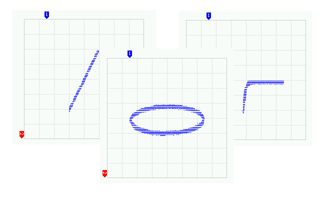
Dead Short
A short-circuit condition is easily distinguished from all others.

Resistor, 100Ω
As a resistor is defined by its voltage-vs-current slope, we expect a straight line here.

Resistor, 1kΩ
Should be the same as the previous picture, but with a lower slope value.

Capacitor, Alum. Electrolytic, 4.7μF
Reactance of a capacitor tends to create an ellipse.

Diode
Standard MBR1100. You can see that the component is an open when positively biased and an approximate short-circuit when the component is negatively biased.

MOSFET, Vg = 0.0V
An IRF530 MOSFET in a TO-220 package. The MOSFET with 0.0Vg looks much like the diode.

MOSFET, Vg = 4.0V
As we increase Vg, we can see that the MOSFET begins to conduct.

MOSFET, Vg = 5.0V
We can only go to 5.0V, but we can see that the component is approaching a short circuit as Vg increases.

- article
- current-sensor
- curve-tracer
- dispatch
- fan-controller
- fixed-point-math
- load-cell-sensor
- meta
- reference


 RSS
RSS
2
assembly
5
buffer
31
c
3
current sensor
28
curve tracer
2
fan controller
6
fixed-point math
4
interrupt
3
KiCAD
3
labview
5
layout
6
msp430
4
pelican
18
pic24
29
project
12
python
2
Q1.15
4
schematic
10
serial
3
solidworks
2
task manager
2
theme
3
tkinter
9
uart
9
xc16