-
 Project Curve Tracer: Bringing Up the New Boards
- Date Tue 31 May 2016
- By Jason Jones
- Category curve-tracer
- Tags curve-tracer c curve tracer schematic
Current Board Status
The board is currently working and working well, but there were a few bumps along the way. There always are, but - in this case - they were slightly more than expected.
Surprises
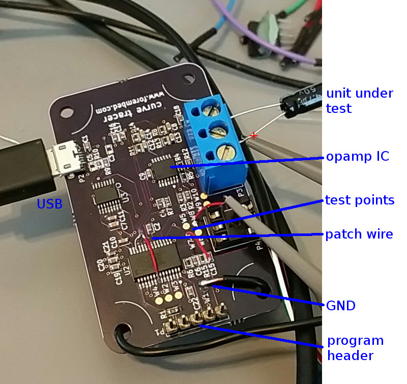
After the last revision, we thought that the kinks were worked out of the schematic. There were still a couple of surprises left for us, but nothing that couldn't be fixed with a couple of trace cuts and a patch wire.
DAC Output Impedance
This was the first surprise of the day. After going through a quick software port during which we disabled the on-chip opamps and shifted the DACs directly to the pin outputs, the waveforms observed were very distorted. It turns out that the DACs have a very high output impedance and are incapable of driving any but the highest of impedances themselves. This led us to re-connect the opamps in software and to add a patchwire. Fortunately, this is the only hardware patch we have had to do to the board. Unfortunately, we had a hardware patch.
Current-Sense Gain
We started this schematic with a full range of -2.5mA to +2.5mA. During this testing, we have expanded that range by reducing the current-sense gain of the differential opamp to 10 from 100. This should improve the output response and brings the circuit closer to the current ranges of the Huntron Tracker 2000 that we are targeting as a respacement. Now the full range is -25mA to +25mA.
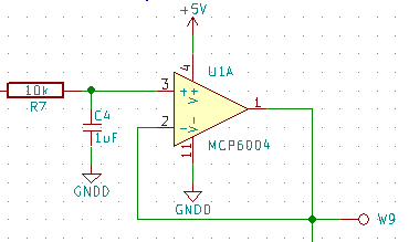
Adjusting Filters
This one was not entirely unexpected as there is always a bit of tuning and adjustment. It turns out that the noise that we had experienced on the previous revision was a result of PWM present on the current-sense reference pin. The noise was still present on this iteration of the layout. A simple RC filter adjustment from 1kΩ to 10kΩ squashed the problem. Since we had a patch wire on this board anyway, we will probably add another stage to this filter to make it bulletproof.
DAC Update Rate
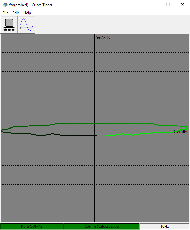
In the midst of seeing what some components looked like on the curve tracer, we found one result that was a bit startling at first:

In this scope capture, we had placed a 4.7μF capacitor on the curve tracer and just happended to be monitoring the waveforms with the scope as well. Note tha the 'envelope' of the current waveform (yellow) is roughly a lagging sine wave, which is what we would expect... but where is all of that choppiness coming from?

If you look closely at the waveform (blue), you can see the small stair-steps caused by the DAC update.
On each update, the DAC voltage changed quickly and the current across the capacitor peaked. On observing this,
we made a software change that ensures that the DAC update is much faster.
Software Strategy
The GUI sends a calculated period based on the user-desired frequency. The period is based on the instruction cycle of the microcontroller, which is 12MIPS. The GUI sends a period, in cycles, based on this instruction cycle.
After a bit of playing with the update rate, it was determined that a period of 1000 is adeqate. The period of 1000
corresponds to 83.3μs. Whenever a period is requested that is greater than 2000, the microcontroller will decrease
the period until it is less than 2000 and decrease the omega by the same increment. The GUI is unaware of this particular
calculation and translation is done completely on the microcontroller.
1 2 3 4 5 6 7 8 9 10 11 12 13 14 15 16 17 | void changePeriod(void){
uint16_t newPeriod;
q16angle_t newOmega = HIGH_SPEED_THETA_INCREMENT;
dacSamplesPerAdcSamples = 1;
DIS_getElements(0, &newPeriod); // retrieve the commanded period
while(newPeriod > 2000){
newPeriod >>= 1;
newOmega >>= 1;
dacSamplesPerAdcSamples++;
}
omega = newOmega;
theta = 0;
PR1 = newPeriod; // PR1 is the TMR1 period register
}
|
HIGH_SPEED_THETA_INCREMENT is a constant that is based on the number of samples that are to be sent to the curve
tracer GUI. This is a constant because the angle progress per ADC sample is maintained as the same throughout the
operation of the device. Only the timer interrupt period changes. In this case, the HIGH_SPEED_THETA_INCREMENT
is calculated to 1024, which translates to about 5.6°.
The code does a bit more than is described above. By changing the DAC update rate without changing the ADC update
rate, there needs to be some method to keep track of when each is intended to occur. We use dacSamplesPerAdcSamples
to keep track of this so that the period may be re-scaled when it is sent back to the GUI.
1 2 3 4 5 6 7 8 9 10 11 12 13 14 15 16 17 18 19 20 21 | void _ISR _T1Interrupt(void){
theta += omega;
DAC1DAT = q15_fast_sin(theta) + 32768;
DAC2DAT = q15_fast_sin(theta + 32768) + 32768; // theta + 180 deg
/* reset sampleIndex on every cycle */
if(theta == 0){
if(xmitActive == 0){
sampleIndex = 0;
}
AD1CON1bits.SAMP = 0;
}else if((theta & (HIGH_SPEED_THETA_INCREMENT-1)) == 0){
AD1CON1bits.SAMP = 0;
}
IFS0bits.T1IF = 0;
return;
}
|
The T1 interrupt simply advances theta in increments of omega, both of which were set in changePeriod(). By
advancing theta, we can see in lines 4 and 5 that the DAC outputs are modified appropriately to generate the
sine wave.
The T1 interrupt is also responsible for starting the ADC at the appropriate time so that the samples are taken evenly
throughout the waveform. This is why the ADC1CON1bits.SAMP bit is being cleared under certain conditions.
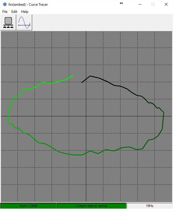
Results

This picture also takes into account the gain adjustment of the current sensor circuit, mentioned previously
Results
The results are quite good compared to the previous results.
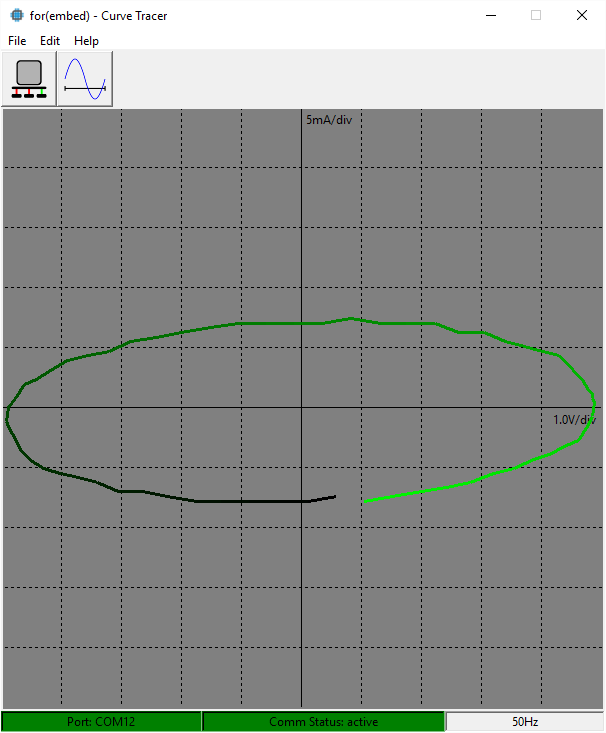
There is still a small ripple observed on the waveform, which - I believe - is the result of the PWM filter on the current-sense reference. The next revision will make this a 2-pole filter, which should remove that ripple quite well.
There is also a small vertical offset that can be observed. We will implement a software calibration that occurs at startup or on external command to remove this offset.
It looks like one more round of hardware revision and a couple of tweaks to GUI software will put us ready to release!
As always, the most recent working data may be found on github.
- article
- current-sensor
- curve-tracer
- dispatch
- fan-controller
- fixed-point-math
- load-cell-sensor
- meta
- reference


 RSS
RSS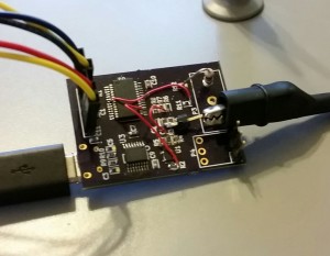
2
assembly
5
buffer
31
c
3
current sensor
28
curve tracer
2
fan controller
6
fixed-point math
4
interrupt
3
KiCAD
3
labview
5
layout
6
msp430
4
pelican
18
pic24
29
project
12
python
2
Q1.15
4
schematic
10
serial
3
solidworks
2
task manager
2
theme
3
tkinter
9
uart
9
xc16