-
 Project Curve Tracer - Layout
- Date Thu 11 February 2016
- By Jason Jones
- Category curve-tracer
- Tags curve-tracer curve tracer kicad layout
If you haven't read the project documentation up to this point, you may want to go back to the beginning.
If you are ready to dive into the layout, then lets get started!
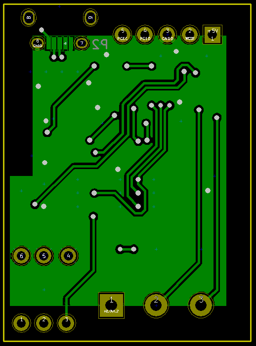
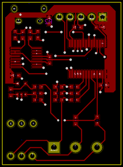
This will probably be a short post. The layout process was fairly straightforward and resulted in a board 1.1" x 1.5", 2-layer. I did make a couple of funny design choices that should probably be explained. Lets take a look at the board:
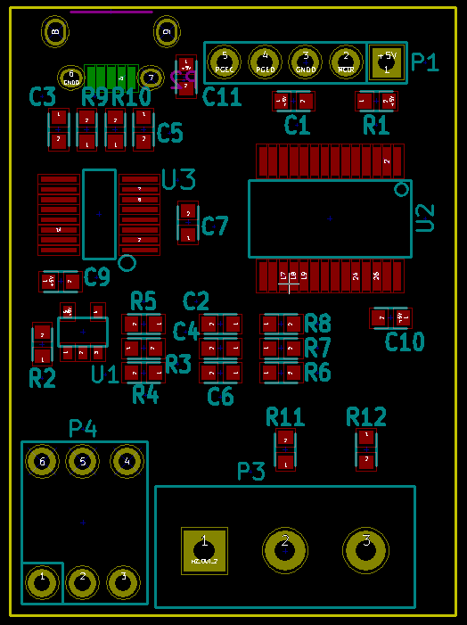
Component Sizing
I have chosen the smallest reasonable packages available for the active parts and 0603 components for the passives. I really like 0603. I can solder 0402, but it gets really annoying. The 0805 package just seems too large.
I/O
P3 is a screw terminal. This makes it so that we can attach any sort of wire we like to the outputs while we are prototyping.
P4 is a 3-pin device on the schematic, so what happened here? As it turns out, a 3-pin spring loaded socket for TO-220 packages was either too expensive or out of stock, but 6-pin sockets are quite readily available and cheap. The result is the P4 footprint.
The USB connector is at the top left on the bottom side of the board. I haven't done many USB connectors, so I am sure to have gotten something wrong, but that is what this revision is all about. All-in-all, I'm happy with the way the board turned out in layout, particularly the size. Perhaps the next revision will incorporate mounting provisions, but we can learn that sort of thing later.
Test Points
One thing that I forgot that you shouldn't - put some test points on your board! I banged this out in an hour and completely missed test points! I'm sure that I can hack a test point on there, but it is nice to be delivered with them!
Electronic files can be found on github.
- article
- current-sensor
- curve-tracer
- dispatch
- fan-controller
- fixed-point-math
- load-cell-sensor
- meta
- reference


 RSS
RSS
2
assembly
5
buffer
31
c
3
current sensor
28
curve tracer
2
fan controller
6
fixed-point math
4
interrupt
3
KiCAD
3
labview
5
layout
6
msp430
4
pelican
18
pic24
29
project
12
python
2
Q1.15
4
schematic
10
serial
3
solidworks
2
task manager
2
theme
3
tkinter
9
uart
9
xc16