-
 Project Curve Tracer - Capacitor Shots
- Date Fri 29 April 2016
- By Jason Jones
- Category curve-tracer
- Tags curve-tracer c curve tracer capacitor
Squashing Bugs
As you recall from the last post, we were able to get a few screen captures of a few components under test, but the pictures were a bit rough. Today, we still have rough pictures, but they are a lot better due to a little effort in reducing bugs and sampling intelligently.
Some of the bugs were found within Dispatch... which deserves a post of its own, but each was dealt with during a major refactor and testing was added to ensure that those bugs don't creep in again at a later time.
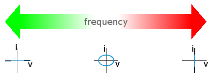
Capacitive Reactance
Today we were able to see some capacitive reactance as we changed the frequency. Note that the screenshots last time were all done at a particular frequency. Now, we chose a 0.22uF capacitor and varied the frequency. We can see the reactance go from nearly open-circuit to nearly short circuit.
We are adjusting the frequency by adjusting 'omega', which is the change in theta over time. As omega increases, so does frequency.
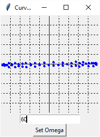
Capacitor, 0.22uF
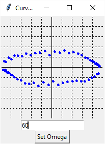
Omega = 60, 11Hz
There is only the smallest deviation from 0mA. As each vertical division is 1.11mA, we are looking at much less than 1mA.
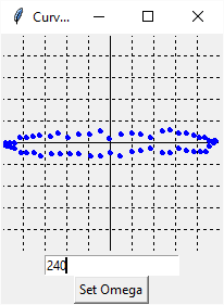
Omega = 240, 44Hz
As we increase the frequency, we can see the ellipse beginning to emerge. Due to some hardware choices made earlier in the project, one can see a fair amount of noise on the trace. We can eliminate this in the next round.
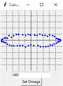
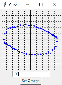
Omega = 480, 88Hz
Now we can clearly see a horizontal ellipse forming. The peak currents are ~1.1mA and the voltage is still able to traverse the entire +/-5V range.
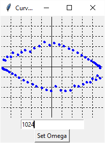
Omega = 1024, 188Hz
Now we have an open 'eye' which is about as close to an ellipse as we have available to us.
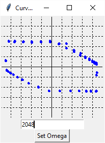
Omega = 2048, 376Hz
And finally, we see the first signs of horizontal clipping. This is where the board can supply no more current and the voltage isn't making it to the ends of the x-axis.
Capacitor, 4.7uF
We expect the 4.7uF to behaving similarly to the 0.22uF, but we should see the behaviors at lower frequencies. On this series, we are going to check a few more 'in-between' frequencies so that we can see what the component looks like throughout the cycle.
Omega = 60, 11Hz
Omega = 100, 18Hz
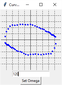
Omega = 120, 29Hz
We are seeing the beginnings of the short circuit on the left and right edges of the trace. This trend will continue as frequency increases.
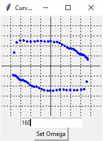
Omega = 160, 11Hz
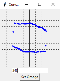
Omega = 240, 44Hz
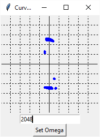
Omega = 2048, 376Hz
Note that there is still a narrow opening, but that if we continue to increase the frequency, the opening would continue to close until it was indistinguishable from a dead short.
What did we Learn ?
As our capacitors are not making true ellipses, particularly at lower frequencies, the 200Ω of resistance in series with the path probably has something to do with it. It would be more ideal to directly connect the opamp output to the device; however, Microchip warned me that there was no current limiting protection on the internal opamps. That leaves me with having to limit the current in other ways. I chose a resistor. The next layout will likely have a dedicated set of opamps for the tasks.
We know that the Dispatch library is working well and that we can change the frequency on the fly by
sending the omega to the omega topic via the serial port. It appears that we are at a point at which
we should cut the next round of hardware. We can do more firmware development while waiting for hardware.
Aside from a few reworks here and there, the harware had definitely proven that it has the base
capability to perform the core operations of the curve tracer, but we have found some shortcomings
of the hardware along the way that we would like to address. The next post in the series will highlight
all of the changes that we wish to make to the form, fit, and function of the unit. After that, we
will have the next boards on the way.
Stay tuned!
- article
- current-sensor
- curve-tracer
- dispatch
- fan-controller
- fixed-point-math
- load-cell-sensor
- meta
- reference


 RSS
RSS
2
assembly
5
buffer
31
c
3
current sensor
28
curve tracer
2
fan controller
6
fixed-point math
4
interrupt
3
KiCAD
3
labview
5
layout
6
msp430
4
pelican
18
pic24
29
project
12
python
2
Q1.15
4
schematic
10
serial
3
solidworks
2
task manager
2
theme
3
tkinter
9
uart
9
xc16