-
 Project Curve Tracer - Next Revision
- Date Mon 02 May 2016
- By Jason Jones
- Category curve-tracer
- Tags curve-tracer curve tracer schematic layout pic24

Project Status
As you have seen with a few screenshots, we have made significant progress since the first post. We have completed a schematic, layout, rework, and created a basic code framework. We have proven that the hardware mostly works as-is, but would like to make some improvements. In this post, we are stepping back from the software for a moment and heading back into hardware land to address some of our concerns.
Temptation
After getting this far, I was actually tempted to change microcontroller series for something a bit faster and more integrated. There are definitely processors out there - like the STM32F series - that would be perfect for this application (high-resolution DAC, built-in USB, etc.). I feel that I would lose some value to what work has been performed thus far and that the PIC24 series is adequate with some modifications, so I will complete this project with the PIC24 series and leave other processors for another day or another requirement.
Communications
The FT230X has been great. I went through a bit of setup, but I haven't even thought about the part since then. It has been seemless. I will leave the schematic for it and the USB connector itself alone.
PIC24 Part Confusion
In one of the first posts, we documented a couple of items:
- We should be using the PIC24FJ part, which requires a capacitor on pin 20 and cannot be assigned to a pin function
- We messed up the programming header pin numbers-to-labels associations
Neither of these required major changes to the board and the reworks were fairly straightforward. We definitely want to correct this on the next schematic..
Analog
On the analog side, we would like to make several changes. The first is that we want to use all external amplifiers. I thought that I was being super clever using the internal opamps, and I still believe that this would be the best solution, but the outputs of the internal opamps are not over-current protected. This is the exact function that I require for this application, so I'm feeling forced to use better external parts. This is unfortunate since it was a large part of the reason that I had chosen this particular micro-controller, but such is life. Moving to an external part should allow us to to a few helpful things on the analog side:
- Eliminate the current-limiting resistor
- Reduce the value of the current-sensing resistor
- Filter the DAC with an RC, which will help smooth the sine waveform
- Further filter and buffer the current-sense reference output as the PWM source could be contributing to the small ripple that we are seeing on the current of the VI plots.
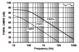
In addition to these goals, we also noted a small deficiency in the current-sensing amplifier. It appeared that - at open leads - there was a small sinusoidal waveform shown on the current sensing output. This is, I suspect, a result of a too-low value for common-mode rejection ratio (CMRR). The datasheet states that the MCP6001 has a typical CMRR of 72dB at DC, but looking at the CMRR vs. Frequency chart, a 1k frequency has a CMRR of ~40dB. We would like a bit more.
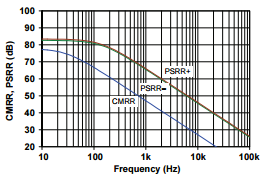
The MCP6L04 appears to be a nice compromise between price and features. In truth, it is a very similar part to the MCP6004, just slightly better all around. It wouldn't surprise me if these two parts came off of the same design and were simply sorted into the proper part numbers.
Physical
It would be really nice if the physical interface were a bit more user-friendly. On the first round, we actually ignored this completely, knowing that getting a board in a reasonable amount of time for software development and discovering the bugs that we had put in place would be worth the sacrifice. This time around, we want to think about how the user might really want to interface with the board.
Test Leads
The typical curve-tracer is equipped with test lead jacks. This is a low-voltage device, so safety jacks aren't necessary, but it certainly would be nice if your existing multimeter leads were compatible. Most multimeters use standard 4mm 'safety' jacks. This would be great, but the majority of these jacks are of the 'panel mount' type and are not at all easy to place on a board-only assembly. So for the moment, I will leave the screw terminals on the board. In the future, if we box this project up, then we will likely put a large safety jack on the front so that we can use standard multimeter leads.
Three-Terminal Device Testing
There still exists the need - although not the software - to test 3-lead components such as transistors and MOSFETs. When we last visited this, I chose to place a 6-pin socket on the board since 3-pin sockets appeared to be so much more expensive. I still believe this to be the right call as we can always toss a 3-pin socket or other similar device in its place.
Test Points
Simply overlooked on the last round was a set of test points. As a result, there were several items that were simply soldered on to the pins directly. This works, but isn't very user friendly. This time around, we will spend a bit more time on test points. Places for test points:
- Ground
- Some micro-controller pins
- Current-sense output
- Current-sense reference
- Low-side output voltage
Mounting Considerations
Again, it would be great to place this inside an enclosure of some sort. Since this is going to be for guys like me - people who like to see the board components - I am opting to use one of the Sick of Beige footprints. These cases are clean looking and cheap. Since our board is a bit tight for the 50x31mm case, we will target the 60x37mm footprint for our next layout.
Wrapping Up
I won't go through the block-by-block like last time since the target hasn't really changed very much. I will upload the new schematic and layout files to github for your viewing pleasure.
As a final note, take a look at the most recent version of the curve tracer screenshot:
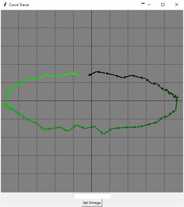
I had wanted to make it look like the old familiar green and grey of the huntron tracker 2000, but I got the idea to color-code each segment around and I really liked the way it highlighted the start and end of the waveform.
- article
- current-sensor
- curve-tracer
- dispatch
- fan-controller
- fixed-point-math
- load-cell-sensor
- meta
- reference


 RSS
RSS
2
assembly
5
buffer
31
c
3
current sensor
28
curve tracer
2
fan controller
6
fixed-point math
4
interrupt
3
KiCAD
3
labview
5
layout
6
msp430
4
pelican
18
pic24
29
project
12
python
2
Q1.15
4
schematic
10
serial
3
solidworks
2
task manager
2
theme
3
tkinter
9
uart
9
xc16