-
 Project Curve Tracer - Using the On-Die Opamp
- Date Fri 26 February 2016
- By Jason Jones
- Category curve-tracer
- Tags curve-tracer buffer c curve tracer pic24 project xc16
Intro
In the previous post code-oriented post, we got the DAC generating waveforms of reasonable frequencies. Unfortunately, a DAC usually has a high output impedance, which will distort our signals if we place it in the wrong circuit. Fortunately, we can make up for this using the on-board operational amplifiers as 'buffers' or 'voltage followers'. Their job is to simply take the input voltage and reflect it on the output with a low output impedance. This post will focus on getting the op-amps running in this mode.
Board Patches
As mentioned in the last post, there were some schematic errors. We aren't going to go into all of the changes, just the necessary ones to make this board work. We did 3 things:
- Cut the trace from U2, pin 7 to U1, pin1.
- Applied a patch wire (in red) between U2, pin 7 and the output on R11.
- Used a solder-bridge to short U2 pins 25 and 26.
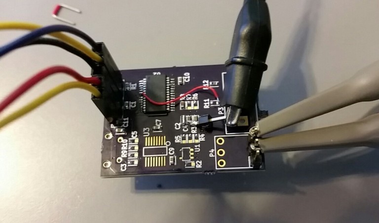
Performing these operations shunts our opamp outputs to the desired outputs. More changes will be made later.
Buffer Amplifier
Desired Circuit
The buffer amplifier is likely the simplest opamp circuit out there. If you don't understand how it works, follow the link. The simplest idea is that Vout always equals Vin.

On-Chip Opamp
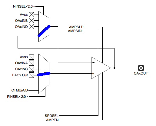
The on-chip amplifier is very configurable. We are going to use the PINSEL and NINSEL registers to make our on-chip amplifier conform to the buffer connections above. See the blue lines below. The OAxOUT pins are our pins 7 and 26 on our device.
Code
We can use just a couple of lines of code to configure the opamp pins. Looking at the datasheet AMPxCON:
- AMPEN = 0 ( opamp disabled)
- AMPSIDL = 0 (idle mode doesn't matter)
- AMPSLP = 0 (sleep mode doesn't matter)
- SPDSEL = 0 (low bandwidth)
- NINSEL = 101 (voltage follower config)
- PINSEL = 101 (DAC input)
We could load these all at once, but I am not certain that the compiler would recognize and optimize sequential register manipulations, so we will simply look at all of the 1's and calculate the hex value, which is 0x002d.
The final statement is to turn the opamps on using the AMPEN bit.
1 2 3 4 5 | TRISBbits.TRISB3 = TRISBbits.TRISB15 = TRISBbits.TRISB14 = DIO_INPUT;
ANSBbits.ANSB3 = ANSBbits.ANSB15 = DIO_ANALOG;
AMP1CON = AMP2CON = 0x002D;
AMP1CONbits.AMPEN = AMP2CONbits.AMPEN = 1;
|
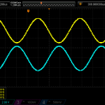
Test
The scope output shows that our buffer amplifiers are working perfectly!

- article
- current-sensor
- curve-tracer
- dispatch
- fan-controller
- fixed-point-math
- load-cell-sensor
- meta
- reference


 RSS
RSS
2
assembly
5
buffer
31
c
3
current sensor
28
curve tracer
2
fan controller
6
fixed-point math
4
interrupt
3
KiCAD
3
labview
5
layout
6
msp430
4
pelican
18
pic24
29
project
12
python
2
Q1.15
4
schematic
10
serial
3
solidworks
2
task manager
2
theme
3
tkinter
9
uart
9
xc16