-
 Current Sensor Board - Testing with a DC Motor
- Date Fri 18 March 2016
- By Jason Jones
- Category current-sensor
- Tags current-sensor current sensor project dc-motor
In previous posts, we tested the DC performance of the current sensor board. In this post, we are going to test the current sensor board using a typical toy DC motor as the load.
DC Motors
A DC motor runs from a DC power supply, but the motor currents are …
more ...-
Project Curve Tracer: Configuring the UART
- Date Fri 11 March 2016
- By Jason Jones
- Category curve-tracer
- Tags curve-tracer c curve tracer interrupt pic24 project serial usb xc16
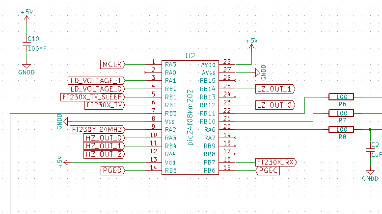
Intro
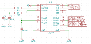
We have the most basic elements of the curve tracer working, but we have no way to interface with it other than hooking up the Microchip debugger and downloading array variables. In this installment, we are going to make the first steps toward getting data to the PC using …
more ...-
Project Curve Tracer: Configuring the Oscillator
- Date Thu 10 March 2016
- By Jason Jones
- Category curve-tracer
- Tags curve-tracer c curve tracer pic24 project xc16
If you have no idea what this is about, go back to the Curve Tracer Requirements Post!
Intro
In previous posts, we have been using the maximum speed 32MHz (16MIPS) oscillator. This oscillator is prone to some error and we would like to eliminate that error. In this post, we …
more ...-
Project Curve Tracer - Implementing the Task Manager
- Date Fri 04 March 2016
- By Jason Jones
- Category curve-tracer
- Tags curve-tracer c fixed-point interrupt pic24 project task manager xc16
Intro

From this point on, there are various tasks that need to occur deterministically, but not necessarily via an interrupt. We are going to implement a task manager for this purpose. For readers, this may be familiar. We already implemented the task manager for the MSP430 a few weeks ago …
more ...-
Current Sensor Board - Testing
- Date Thu 03 March 2016
- By Jason Jones
- Category current-sensor
- Tags current-sensor buffer current sensor project
For a project introduction, go back to the first post!
Intro
So, if you are already familiar with the project, you know that I was looking for a quick general-purpose current-to-voltage converter with a low-impedance output. I received boards this weekend and was able to solder together the module today …
more ...-
Project Curve Tracer - ADC Input
- Date Wed 02 March 2016
- By Jason Jones
- Category curve-tracer
- Tags curve-tracer adc c curve tracer pic24 project xc16
Intro
Up to this point, we have focused on generating signals without necessarily observing those signals. In this post, we will begin to give the microcontroller the capacity to observe those signals using the Analog-to-Digital Converter (ADC).
ADC Requirements
There are 5 signals to be observed:
- LD_VOLTAGE_0 - this is the …
-
Project Curve Tracer - Setting Up PWM as a DAC
- Date Mon 29 February 2016
- By Jason Jones
- Category curve-tracer
- Tags curve-tracer c curve tracer fixed-point math pic24 Q1.15 xc16
Intro
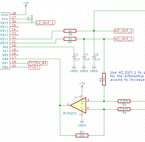
In the initial schematic, you will recall that U1 is an opamp in the differential configuration. This means that the voltage at the reference input will be the 'center' or '0' voltage of the output. We decided to place a small RC filter at the input of that opamp …
more ...-
Project Curve Tracer - Using the On-Die Opamp
- Date Fri 26 February 2016
- By Jason Jones
- Category curve-tracer
- Tags curve-tracer buffer c curve tracer pic24 project xc16
Intro
In the previous post code-oriented post, we got the DAC generating waveforms of reasonable frequencies. Unfortunately, a DAC usually has a high output impedance, which will distort our signals if we place it in the wrong circuit. Fortunately, we can make up for this using the on-board operational amplifiers …
more ...-
Project Curve Tracer - Schematic Errors
- Date Thu 25 February 2016
- By Jason Jones
- Category curve-tracer
- Tags curve-tracer curve tracer layout pic24 project schematic
As always, there are some schematic errors. This is one of the issues with highly integrated ICs, it is so easy to mix up the pins! Maybe I should stop doing schematic and layout so late at night...
- Vcap should be on pin 20, nothing else. This error arose from …
-
Project Curve Tracer - DAC Initialization and Utilization
- Date Tue 23 February 2016
- By Jason Jones
- Category curve-tracer
- Tags curve-tracer c curve tracer pic24 project
Go back to the first post to get some background on this project!
Hardware Patch
Just a couple of notes before we begin coding. I was using the pinout for the "PIC24F" part on the datasheet whereas I should have been using the "PIC24FJ" part. This will involve a small …
more ...- article
- current-sensor
- curve-tracer
- dispatch
- fan-controller
- fixed-point-math
- load-cell-sensor
- meta
- reference


 RSS
RSS
2
assembly
5
buffer
31
c
3
current sensor
28
curve tracer
2
fan controller
6
fixed-point math
4
interrupt
3
KiCAD
3
labview
5
layout
6
msp430
4
pelican
18
pic24
29
project
12
python
2
Q1.15
4
schematic
10
serial
3
solidworks
2
task manager
2
theme
3
tkinter
9
uart
9
xc16